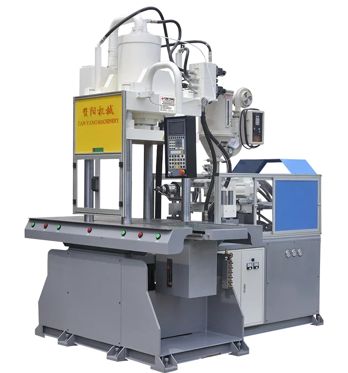
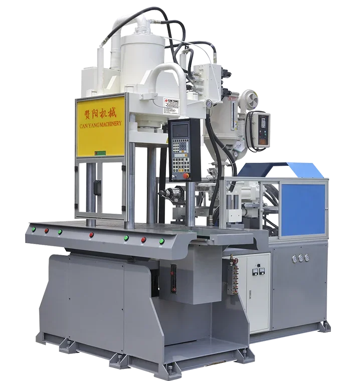
Rotary table
Rotary Table Vertical Injection Molding Machine
Loading, molding and unloading happen at different positions at the same time. For parts whose cycle can be split into parallel work.
What it suits
Automation starts at how the insert arrives, is oriented and is checked, not at the robot that picks it.
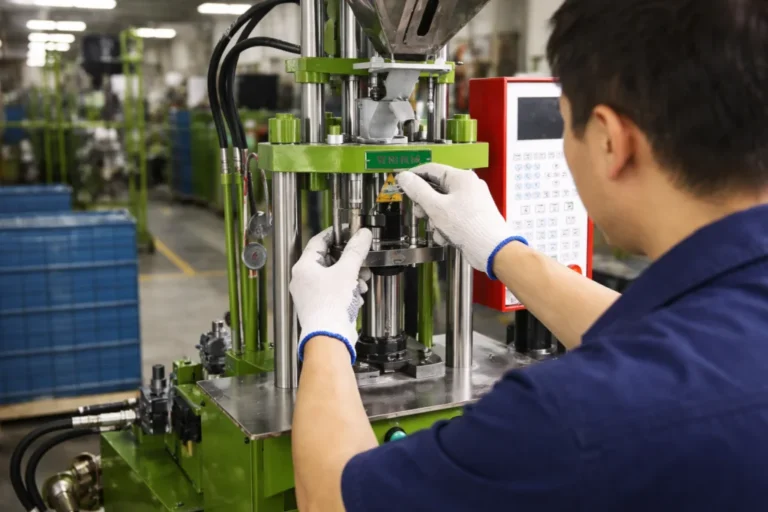
Connector assemblies, terminal blocks, harness ends, coil bobbins and small brackets where the same insert repeats for long runs. Parts whose value sits in repeatable placement rather than in size.
PA6/PA66, PBT, PPS, PP and PC for the body, with TPE or TPU where a grip or a seal is molded. The material matters less here than the insert's own dimensional spread.
An automated cell needs one short, fixed path between where the insert waits and where it has to land. A vertical clamp gives that: the nest is exposed at a known height, the tool closes downward along the same axis the gripper approaches, and the finished part arrives where that gripper or a second one can take it. Loading, clamping and take-out stay in separate zones, so the robot never reaches into a closing tool, and that separation is what keeps the sequence simple.
Before a robot is considered, three things have to be settled: how inserts arrive, in trays, on tape or from a bowl; how they are oriented so that only one direction can be picked; and how presence and seating are detected at the nest. If an insert can arrive tangled, bent or with flash, no gripper fixes that, so feeding and orientation is where the cell is actually designed. Only then are the pick-and-place motion, the reject handling and the cycle budget defined.
Whether insert quality is consistent enough to be fed and picked at all. Which interface the machine exposes for the robot, and who owns the sequence, the gripper and the integration between suppliers. What stops the cycle when an insert is missing or tilted, and what happens to a half-finished cycle after a stop.
Loading, molding and unloading happen at different positions at the same time. For parts whose cycle can be split into parallel work.
What it suitsWhile one table molds, the other is open for loading. The platform for parts whose insert takes as long to place as the shot takes to run.
What it suitsA cell can lose cycles to inserts that arrive out of position, to double picks, to a gripper that marks a light part, and to a check step that takes longer than the loading it replaced. Whether the cell keeps up with the mold is decided by feed consistency, nest design, sensor choice and placement, robot path, interlock logic, the cycle budget and where responsibility for integration is written down.
Naming a risk is not the same as removing it: which of these applies to your part is settled in technical review.
Robots, feeders and vision take over loading and take-out, but the cell is designed from how the insert is fed.
Read the solutionA photograph of the part with the insert in place, the plastic grade and the mold size start the review. Which of the points above applies to your part is settled there, not on this page.