Sliding table
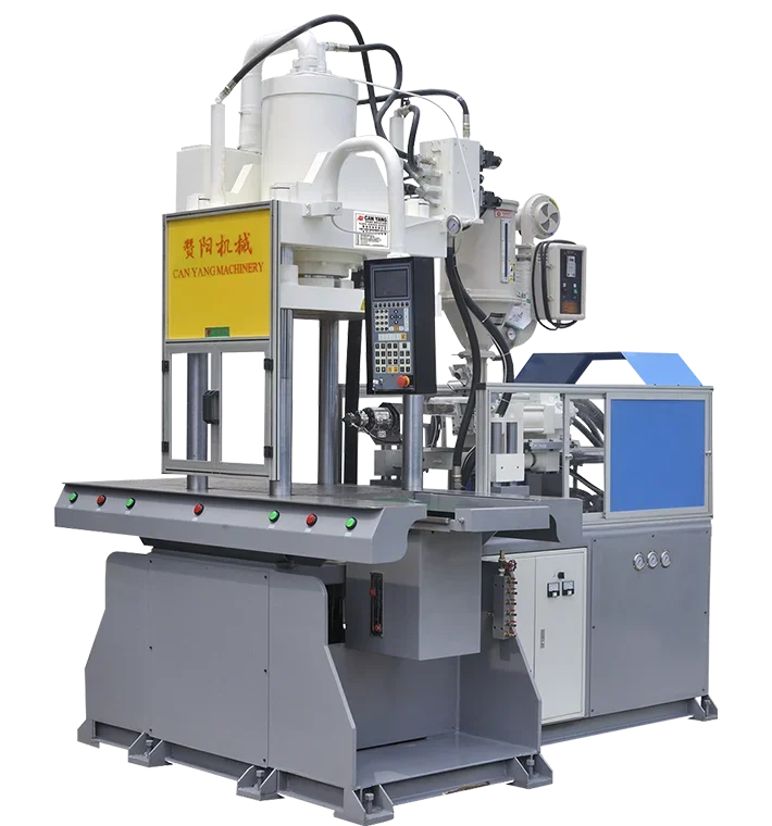
Sliding Table Vertical Injection Molding Machine
Loading happens outside the clamp while the machine keeps its cycle. The first step up from a single station, without paying for a second table.
What it suits
A terminated cable is laid in an open lower mold and the plug body is molded around it.

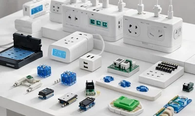
Overmolded plugs and connector boots on cable ends that are already cut, stripped and terminated. Strain reliefs, Y-splits, molded junction sleeves, grommets and USB or power cord terminations.
PVC, TPE, TPU and TPV for the molded body, with the jacket and insulation specified separately because the melt has to bond to them without melting them. PA and PBT appear where the overmold is a rigid housing rather than a flexible boot.
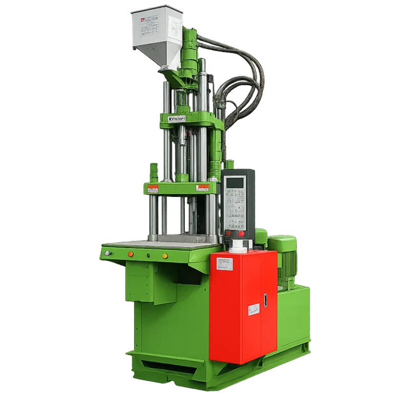
A horizontal platen forces a long cable run to be folded around the tool, so the wire path crosses the parting line where nobody can see it. With a vertical clamp the tool opens upward and the lower half stays flat and exposed at operator height, so the whole run can be laid into its groove and checked. Gravity holds the cable in the groove while the upper half comes down, and the operator's hands stay outside the closing area. The conductor is positioned before clamp force arrives instead of being dragged into place by the closing mold.
An operator seats the cable in the locating groove of the fixed lower half, then closes a manual clamp or drops a pin behind the jacket, outside the molded zone. Because this loading step is longer than the shot on most of these parts, the structure follows it: a single station when loading is quick, a sliding table when the nest has to sit outside the clamp, a rotary table when several steps run in parallel.
Whether the conductor or the insulation gets crushed where the tool shuts off on the jacket. Whether the boot bonds to the jacket well enough to survive a pull test, and whether the cable exit shows marks the end customer will reject. Whether one operator can keep pace with the cycle at the cavity count being quoted.
Loading happens outside the clamp while the machine keeps its cycle. The first step up from a single station, without paying for a second table.
What it suitsWhile one table molds, the other is open for loading. The platform for parts whose insert takes as long to place as the shot takes to run.
What it suitsThe wire can be pinched at the shut-off, the body can short-shot at the far end of a long flow path, flash can appear along the cable exit, and a weld line can leave a seam where the boot has to seal. Whether any of this shows up is decided by groove and shut-off design, gate position, material viscosity, injection speed, clamp force and how consistently the cable is seated. Melt temperature relative to the jacket compound is part of the same judgment.
Naming a risk is not the same as removing it: which of these applies to your part is settled in technical review.
A second plastic body is molded onto a part that already exists, and that boundary is where the difficulty sits.
Read the solutionTwo lower halves move under one clamp, so loading and the shot stop competing for the same minutes.
Read the solutionA photograph of the part with the insert in place, the plastic grade and the mold size start the review. Which of the points above applies to your part is settled there, not on this page.