Single station
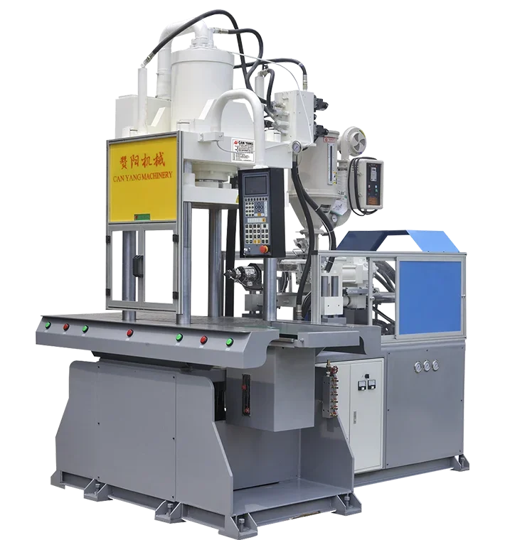
Single Station Vertical Injection Molding Machine
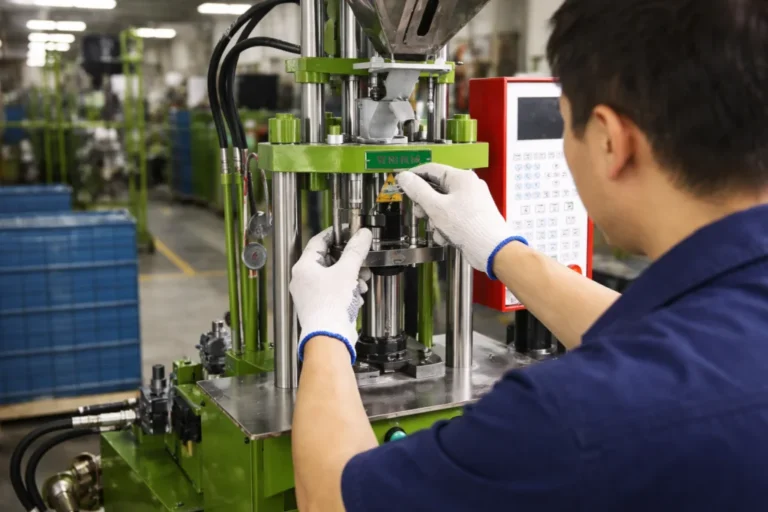
The open working area in its simplest form: place the insert by hand, clamp from above, take the part out. The baseline every other platform is measured against.
What it suits
Terminals stand upright in the lower cavity and the housing is molded around them, so each pin is visible seated.
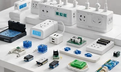
PCB headers, terminal blocks, and board-to-board or wire-to-board connector bodies. Crimp terminal assemblies and contact carriers molded into a housing. Seal rings and busbar end caps formed over a metal contact.
PBT, PA6/PA66, PPS and PPA for housings, often glass-filled where pin pitch is fine and walls are thin. The polymer has to bond to or seal against the plating on the terminal.
Terminals are small, upright and easy to tilt, and a tilted pin is only visible while the tool is open. A vertical clamp leaves the lower half flat and exposed, so the whole pin array is in view from above and can be checked before the upper half descends. Gravity holds the pins in their locating holes instead of letting them hang, and the closing motion travels along the pin axis rather than across it.
Terminals arrive in a carrier strip or a tray and are seated on locating pins in the lower cavity, then checked for full seating and tilt before clamp close. Manual loading with a nest gauge serves the smaller arrays; pick-and-place from carrier tape takes over when the pin count per shot is high.
Whether pin height and position hold over a long run rather than over a few shots. Whether plastic flashes at the terminal exit, and how the housing seals against the plating. Whether a change in the terminal stamping forces the tool to be re-qualified.
The open working area in its simplest form: place the insert by hand, clamp from above, take the part out. The baseline every other platform is measured against.
What it suitsLoading, molding and unloading happen at different positions at the same time. For parts whose cycle can be split into parallel work.
What it suitsA terminal can move once injection pressure arrives, thin walls between contacts can short-shot, flash can form at the shut-off around the pin, and locating pins wear until the array no longer sits at the same height. What appears is decided by pin support in the cavity, gate and runner layout, wall thickness, injection profile, cavity count and how the terminal is held during clamp-up.
Naming a risk is not the same as removing it: which of these applies to your part is settled in technical review.
The insert goes into the mold before the shot, so plastic forms around metal instead of being assembled onto it.
Read the solutionSeveral lower halves travel around a fixed clamp, so loading and molding run at once on different stations.
Read the solutionRobots, feeders and vision take over loading and take-out, but the cell is designed from how the insert is fed.
Read the solutionA photograph of the part with the insert in place, the plastic grade and the mold size start the review. Which of the points above applies to your part is settled there, not on this page.